The N – Factor
I looked at the floor. It was covered with noise.
All my audio life I have bumped the noise floor. That pernicious energy that seems to fill all the cracks and crevices of my space-time. So what is this bane of my audio life?
Webster says that it is “any sound that is undesired or interferes with one’s hearing of something.” OK, that’s a good place to start. Snap, crackle, and pop, mixed randomly is the wallpaper of space and time. EVERYTHING shakes, rattles and rolls with energy. It is the vibrations of the atoms and was defined by Ludwig Boltzman in the last Century. In conductors it creates a signal voltage – our friend noise, you know, that hiss in your sound system, in electronic stuff we call it Johnson-Nyquist Noise.
The amount of noise power is the product of the resistance, temperature, and bandwidth, then you mix in a constant, take the square root, and you get the voltage produced. Typical numbers for a resistor of 50 ohms at 273 degrees Kelvin (room temperature) and the audio band (20-20kHz) would be about -136 dBv or about 0.13 microVolts (130 nanovolts) RMS. That is the noise floor for 50 ohms at room temperature; you can’t get any quieter than that unless you lower one of the variables. If you have a technical inclination the equation is:
Noise (power) = Square root (4 x 1.38×10-23 x Temp x Resistance x Bandwidth)
This is the Noise Floor, the level that you cannot get below. If you build an amplifier, measure its output noise and subtract the gain of the ampler you get a higher noise level than the Noise Floor. This is the noise added by the amplifier and is called the Noise Factor, how much noise the amplifier added to the signal. If we add the Noise Floor to the Noise Factor we get what we call the Equivalent Input Noise, the amount of noise that you would get if the amplifier was perfect.
All semiconductors (transistors) are basically glass, which is an insulator. Add some extra atoms to the glass and it becomes a ‘semi-conductor’ of electricity. But it does so while making lots of Johnson-Nyquist or Thermal Noise.
Tubes have it worse, they run off of heat, thermonic valves they used to be called. They work by heating the cathode to boil off electrons, which sounds like a waterfall.
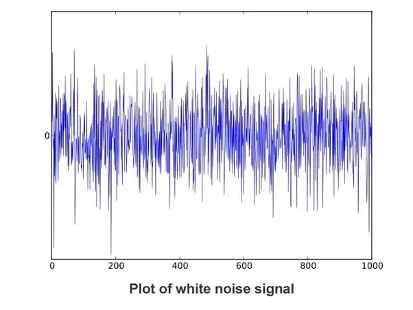
But hiss is the noise of nature. Tune between radio channels and you will hear hiss that is the noise of the Big Bang, the noise of the universe, it’s pervasive. Here is an image of energy over time of noise. It is a random collection of snaps, crackles, and pops (pour out a bowl of Rice Krispies, add milk, and hear the white noise, humor me).

This is a ‘snapshot’ of the energy at any given unit of time. While it doesn’t look like it, over time every frequency in the bandwidth is present. Energy from everything we do is simply added to the Noise Floor; because what we want to do requires amplification and it all gets noisier pretty quickly.
What all this says is that the first source of noise has the greatest effect on the end product, in our case the reproduction of recorded music.
The N – Factor
The question one asks is how do we lower the Noise Factor of the first stage of an audio system?
We know that Temperature, Resistance, and Bandwidth are the variables. Sure we can cool it, make a lower resistance, or limit the bandwidth – but each is a rabbit hole and comes with heavy down sides.
How about we cheat?
Yes, we can cheat Bolzman’s equation in effect by changing the value of Boltzman’s number, the constant in the equation, that 1.38×10⁻²³.
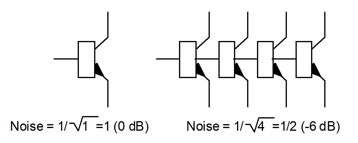
We will use the characteristic noise of the silicon against itself. The noise is random; when you sum two noise sources the resulting new noise will have less power, specifically the square root of it.
This introduces what I call the N-Factor. Not the Noise Factor but the Number of front-end semiconductor gain cells doing the amplification in parallel, for this is a circuit condition in which the Noise Factor goes down. If you do this in the first transistors of the gain cells in a system the noise is reduced by the square root of the number of them. Put four devices in parallel, square root of 4 is 2, the noise is cut by 1/2 (6dB), and use 9 devices and the reduction is 3 or roughly 10 dB. N is the number of devices.
Shouldn’t the noises of each add together? Yes, they do, but the noise is uncorrelated. That means the noise little bit (not digital bits) or ‘quanta’ of the noise has no relationship to each other’s noise quanta; each is truly random. So how does this work?

Each device makes and adds its own noise, but each noise is random snaps, crackles and pops, they don’t each make the same noise at the same time. When one noise is a positive burst another is negative and the sum is less than either so the overall noise goes down. The two noises are uncorrelated.
This does raise the cost of the stage. Good low noise devices are expensive to begin with and needs to be screened (hand labor) but it is the only way to get physics to work for us and not against us in the noise floor battle. It also has a major effect on resolution, clarity, and soundscape, but that is a separate story for another time.
The reason for this discussion of semiconductor noise is that I used this technique in creating the Black Swan Phono Preamplifier. The Moving Magnet input goes through a cartridge load optimization module that lets you set the loading from the front panel by ear and then directly into a “Quadcell” of four parallel low Noise Factor wide bandwidth gain cells. The cell’s gain is 20dB; the input is typically set to around 50 kOhms and a user-selected capacitance. That is a noise floor of 108 dBv or 4 microVolts. Sounds pretty noisy, too noisy to match what we hear. What saves the day is the RIAA equalizer that follows this. The RIAA Equalization both cuts the highs and boosts the lows; it measures very well and sounds good. It has an amazing effect on clarity and resolution. All of this is covered in my musing on Definition, Resolution, and Clarity.
The Moving Coil gain cell is different. It employs a much lower resistance (100 ohms typically) but more important it is a differential input amplifier cell. It ignores the signal referenced to ground and only cares about the difference between the positive and negative inputs taking advantage of the common-mode noise cancellation of such cells. When you operate the MC input in the unbalanced mode one side is grounded making it single ended to the outside world while still working balanced on the inside.
A final note about the Swan system – The internal wiring for the inputs is not run on printed circuit boards. I found that these microvolt and microampere signals are perverted by the fiberglass and solder mask surrounding the copper foil traced as well as the metal in the chassis. All the wiring is small diameter single wires that are Teflon coated with an air surround inside an RF shielded non-ferrous die cast chassis. This way I was able to limit the low level signals to a maximum of three inches on the Circuit Boards.
